 |
Half Wave Rectifier
Since a capacitor input filter only draws current from the rectification circuit in short pulses, the frequency of the pulses is half that of a full -wave circuit, therefore the peak current of those pulses is so high that this circuit would not be recommended for DC power more than 1/2 watt. |
 |
60 Hz Ripple
Depth of ripple slope is dependent on Capacitance and Load. |
 |
Full Wave Center Tapped
A full-wave rectifier uses only one-half of the transformer winding at a time. The transformer secondary rated current should be 1.2 times the DC current of the power supply. The transformer secondary voltage should be approximately 0.8 times the DC voltage of the unregulated power supply per side of the center tap or the transformer should be 1.6 times VDC center tapped. |
 |
120 Hz Ripple
Depth of ripple slope is dependent on Capacitance and Load. |
 |
Full Wave Bridge
The full-wave bridge rectification circuit is the most cost effective because it requires a lower VA rated transformer than a full-wave tapped rectifier. In a full-wave bridge, the entire transformer secondary is used on each half cycle, unlike the full-wave center tapped which only uses one- half the secondary on each half cycle. The transformer secondary rated con-rent should be 1.8 times the DC current of the power supply. The transformer secondary voltage should be approximately .8 times the DC voltage of the unregulated power supply. |
 |
Dual Voltage Supply
A dual complementary rectifier is used to supply a positive and negative DC output of the same voltage. In most cases, the negative current is significantly less than the positive current requirements so the AC voltage and current relationship to the DC voltage and current should be the same as the full-wave center tapped described earlier. |
 |
|
|
 |
|
|
 |
|
|
This fact cannot be overstated. Within the average color TV set, Lethal
voltages
ALL OF THESE VOLTAGES CAN KILL YOU!
|
 |
Secondary Power Supplies
|
Primary Power Supply, Line Rectifier Sections

Line Rectifier Circuits: Line EMI Filter, Automatic Degaussing Coil Hot Chassis
|

Line Rectifier Circuits: Power Transformer, Line EMI Filter, Automatic Degaussing Coil Isolated Chassis |
2...One of the most efficient inductors is the ferrite toroid. It has high "Q" -- low "R" -- and because of its toroidal shape its fields are confined, and therefore has little stray fields. The super star of high "Q" inductors or transformers is the pot core. And of course, don't forget the ferrite bead. Thread the wire through the bead once or several passes and it may be just what the doctor ordered.
3...Decoupling is only as good as the components that you use. The capacitor part of the network should be high "Q" and minimum inductance: the noise is dropped across the inductor, and the capacitor must exclude the remaining noise. Another way of saying it: in a perfect world the inductor is an open circuit to noise (AC) and the capacitor is a dead short -- Zero, Nada, Caput, Zilch; "This here parrot is dead." The slightest inductance in series with that capacitor, and some very high frequency noise will come through like Gang Busters!.... Anyway nuff said.
4...SMT or chip capacitors made of ceramic are best. Also, sometimes in critical circuits, several size caps in parallel are appropriate, e.g., 1ufd || .1ufd || .001ufd, etc. The reason for this is as the capacitors become smaller in value, they also get physically smaller, hence less inductance. However this is less the case with SMT caps: consult your capacitor data sheets for the impedance verses frequency plots. Didn't he just say that?
 |
 |
 |
|
|
|
|
Fig.
4a
 |
Fig. 4b
 |
|||||||||||||||||
|
|
The 1N4002 is for protection (optional) |
|||||||||||||||||
| . | ||||||||||||||||||
|
||||||||||||||||||
|
|
|
|||||||||||||||||
Fig. 5
 |
 |
|||||||||||||||||
|
|
|
|||||||||||||||||
|
|
|
|||||||||||||||||
Fig.
7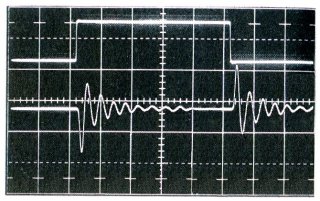 |
Fig.
8
 |
|||||||||||||||||
|
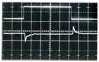
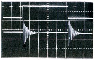
LVR Recovering from load changes C = 0.033 µF |
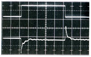
LVR attempting to oscillate C = 0.005 µF |
|||||||||||||||||
|
|
|
|||||||||||||||||
Fig. 9
 |
 |
|||||||||||||||||
|
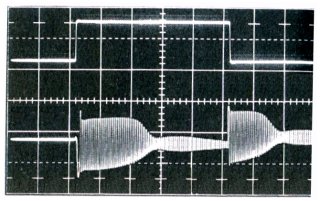
LVR oscillating or Squegging due to OPEN bypass cap C = 0.00 µF |
Caused by squegging oscillation |
|||||||||||||||||
1..Read the data sheet. The needes and capabilities of the regulator are in there somewhere; they might not jump out and bite you right away, but they are there.
2..The use of three terminal linear voltage regulators, like the 78xx and 79xx devices, is fairly straightforward. However, there are a few things to remember: Always bypass -- there's that word again! -- the input pin and the common pin with a ceramic capacitor no smaller than 0.33 ufd, and use absolutely the shortest leads possible (there are some transistors with pretty high ft in that regulator, and if you furnish enough reactance of the wrong kind, Mr. Oscillation will visit you).
3..If your regulator is furnishing power to a capacitive load, and the primary power is removed -- like unplugging a PC card, or disconnecting an experimental setup -- the charge in that capacitive load will cause the secondary or output of the regulator to be more positive than the primary or input. If this reverse voltage exceeds the regulator's ratings it will blow up. To prevent this sort of failure, a diode is placed between the input and output, such that, when reverse voltages are present, the diode conducts preventing damage. (see Figure)
4..There will come a day (or night) when you may need an eight volt regulator, and all you have is a 7805, five volt regulator. By inserting a voltage equal to the difference in the common lead, "Voila," you have 8 volts. You can do this by inserting a zener diode or a low resistance voltage divider (or a pot for variability). If all else fails, insert a series of silicon diodes (cathodes toward Grd.) @ .6 volts per, until you have the desired output.
5..These regulators don't need an output capacitor per se, but a minimum of 1 ufd is recommended to prevent fast load pulses from causing needless error correction by the regulator. As for the primary or input capacitance, it depends on the ripple content from the primary voltage: If the voltage is straight from the rectifier, then obviously large capacitors are required -- assuming a large load on the regulator's output. The greater the difference between the input voltage and the output voltage, the less stringent the capacitor requirements.
6...In the data sheet -- you know, that funny looking piece of paper that causes you to squint, and makes your head feel funny -- In the data sheet, there is information on forward drop, Vfwd, of the regulator at some current. This means that if the primary voltage is near the desired secondary voltage at some current, you may be in "Deep Dudu." The greater the difference between the input voltage and the output voltage, the easier life is: if the rating of the regulator is a 1.1 volt drop at 500 ma, and you have a 5 volt margin -- say -- you are in fairly good shape; if you have, on the other hand, a 10 volt margin, you're in great shape!
 |
 |
|
|
|
Squegging *
Uncontrolled, unwanted or parasitic oscillation, varying in amplitude from some peak value to very low, or completely off. The frequency of this oscillation is high compared to the rate at which its varying.
Suggestions are Solicited, P l e a s e